Geotiff overlay position is slightly off on Holoviews/Bokeh tilemap

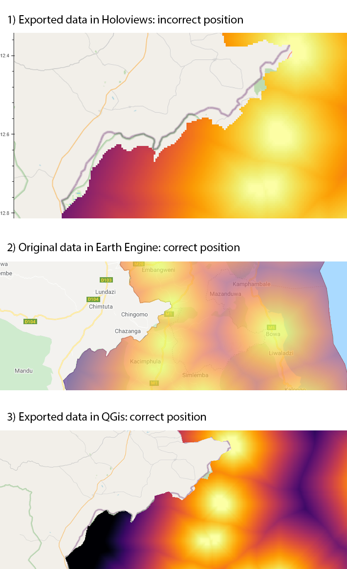
I have a Geotiff that I display on a tile map, but it’s slightly off to the south. For example on this screenshot the edge of the image should be where the country border is, but it’s a bit to the south. (I can only embed 1 image so I included the sceenshots fo the rest of the post too)

Here’s the relevant part of the code:

tiff_rio_500 = rioxarray.open_rasterio( '/content/mw/mw_dist_to_light_at_all_from_light_mask_mw_cut_s3_500.tif' )
dataarray_500 = tiff_rio_500[0]
dataarray_500_meters = dataarray_500.copy()
dataarray_500_meters['x'], dataarray_500_meters['y'] = ds.utils.lnglat_to_meters(dataarray_500.x, dataarray_500.y)
hv_dataset_500_meters = hv.Dataset(dataarray_500_meters, name='nightlights', vdims='cumulative_cost')
hv_tiles_osm_bokeh = hv.element.tiles.OSM().opts(width=1000, height=800)
hv_image_500_meters_bokeh = hv.Image(hv_dataset_500_meters, kdims=['x', 'y'], vdims=['cumulative_cost'], rtol=1).opts(cmap='inferno_r')
hv_combined_osm_500_meters_bokeh = hv_tiles_osm_bokeh * hv_image_500_meters_bokeh
hv_combined_osm_500_meters_bokeh

You can see the live notebook on google colab.

Now this is not the usual “everything is way off” problem that occurs when one doesn’t convert the map to Web Mercator. It is almost perfect, it just isn’t.

The Geotiff is an Earth Engine export. You an see above how it looked originally in Earth Engine (or see live code).
As you can see, the image follows the borders everywhere.

At first I suspected that maybe the export went wrong, or the google map tileset is somewhat different, but no, if I open the same exported Tiff in the QGis application on my windows laptop and view it over the same OSM tilemap as I do in the colab notebook, it looks fine, see again above, part 3 of the screenshot.
Okay, the image does not follow the borders perfectly, but I know why and that’s unrelated (I oversimplified the country border geometry). The point is, that it is projected to the correct location. So based on that, the tiff contains correct information, it can be displayed at the same location as the borders are in the OSM tilemap, but still in my Holoviews-Datashader-Bokeh project it is slightly off.

Any idea why this happens?

I wouldn’t expect manually transforming the coordinates to work particularly well. While it’s a much heavier weight dependency for accurate coordinate transforms I’d recommend using GeoViews.

img = gv.util.load_tiff( '/content/mw/mw_dist_to_light_at_all_from_light_mask_mw_cut_s3_500.tif' )
gv.tile_sources.OSM() * img.opts(cmap='inferno_r')

I’d do the same, but only out of uncertainty; any intuition for why transforming the coordinates in this way would yield results that are off not just by a pixel or half pixel, but by numerous pixels? I can’t quite get why that happens.

Thanks a lot, I will check this out. I’ve just did a google search for “geoviews” “load_tiff” to see how on earth did I not find it on my own even though searching for a solution for weeks, and I see that there are 11 results total on the whole world (now there will be about 2 more more). And also there are 0 mentions of it on the Geoviews, Holoviews, Bokeh websites. Seeing how fundamental the “adding gridded raster data to a tile map” functionality is, it could be useful to include this in the user guides and examples. I would be happy to contribute if it helps…

Also I would be really interested in understanding what the problem here was. I was really surprised to see that the northernmost and southernmost parts of the image were in correct position, but everything in between was “smudged” to the south with the distortion being the heaviest near the center. So it’s not a uniform misalignment (the image being moved), it’s not a uniformly relative misalignment (the image being stretched), but something weirder.

And I also don’t get why it shouldn’t work. Theoretically if I would have sampled a few points, exported them to a CSV and wanted to display them as Points, I should have used lnglat_to_meters as every public example shows this exact scenario. So if I would have sampled one point at the top left corner of every pixel, feed them to lnglat_to_meters one by one, and display them, they would be at the correct position, right? If so, why does it work differently when I read the whole tiff with every pixel in it? If not, then what would be the correct way to sample a value at a specific coordinate and display it on the same tilemap?

Just for the record, I’m like 90% decided to use an alternative solution instead of Geoviews, as I have a somewhat unreliable setup experience with it.

  • I could not install Geoviews to an existing python=3.9 environment on my laptop (through the recommended pyviz channel), it just hanged. I could do it in a new env, with pyton=3.7, so that’s ok for fooling around, but it looks like that if I get an existing project with existing dependencies, I can either add geoviews to the project or not. It’s on Windows, but the problem is not the “it’s famously hard to make GIS software to work on Windows” as I’ve already been through that at one of my previous experiments (the dlls and env vars are all fine now) and that should cause problems while running not while installing.
  • I could not install Geoviews on Colab notebook to be able to run your example. Installing through pip works, but it simply crashes the kernel as soon as it gets to the load_tiff line. Installing conda and installing geoviews through conda takes about an hour or two (not ideal for rapid prototyping) and then it crashes the same way. I tried all the tips and tricks available in various github topcis like installing cartopy and shapely through various ways, without any success. I’ve seen on other bug reports that you are aware of this issue and as it is caused by some underlying libraries, I understand you can not do anything about it.

Seeing how my work process involves a lot of experimentation in Colab, development on Windows and then running production on wherever it is needed by the client (Heroku, Aws Ec2 linux, serverless environments etc), it looks like a huge liability to build on the assumption that I can use Geoviews whenever I want. That’s a shame, as I really like it, and I’m pretty sure that for robust projects with never changing environments it’s a dream, but that’s not my use case.

So my current solution is simply use the rioxarray reproject(), which is a surprisingly easy solution I just didn’t see before. Just before I found it, I’ve created a pretty similar function using pure rasterio, after spending a day unsuccessfully reverse engineering the Geoviews load_tiff, but oh well.

So anyway, the final solution now looks like this:

tiff_data = rioxarray.open_rasterio(tiff_filename).rio.reproject('EPSG:3857') # that's it
hv_dataset = hv.Dataset(tiff_data[0], name='nightlights', vdims='cumulative_cost')
hv_tiles_osm= hv.element.tiles.OSM().opts(width=1000, height=800)
hv_image = hv.Image(hv_dataset, kdims=['x', 'y'], vdims=['cumulative_cost'], rtol=1)
    .opts(cmap='inferno_r')
hv_combined = hv_tiles * hv_image
hv_combined

Glad you found a solution! Geoviews dependencies are indeed quite difficult to manage, which is the main reason we decided to expose tile support in HoloViews. It would be a larger job but I’d be very interested in eventually removing the hard dependency on cartopy and proj4, which are doing the heavy lifting and optionally support a more lightweight mode, which would probably support fewer projections.

1 Like